


HPC Wattage is Making Liquid Cooling the New Norm
Increasing wattage of CPUs and GPUs has been the trend for many years in all types of data centers. These step-wise increases have largely been a background issue addressed by facilities and data center management by limiting rack densities, patch works of hot aisle/cold aisle add-ons and by making sure there was sufficient HVAC and CRAC to handle server nodes blasting more heat out into the data center. Bigger air heat sinks and higher air flows have historically been adequate to manage these incremental increases in heat in enterprise data centers and sometimes for lower density HPC clusters.
One of the takeaways from the 2017 International Supercomputing Conference in Frankfurt, Germany is that for HPC clusters, the wattages of CPUs and GPUs are no longer addressable with air cooling alone. For HPC in the near term and for enterprise computing longer term, an inflection point has been reached in the relationship between server density, the wattage of key silicon components and heat rejection.
This, of course, is becoming critical in HPC as sustained computing throughput is paramount to the type of applications implemented in high density racks and clusters. Unlike most enterprise computing today, HPC is characterized by clusters and their nodes running at 100% utilization for sustained periods. Further, as such applications are always compute limited, cutting edge HPC requires the highest performance versions of the latest CPUs and GPUs. This means the highest frequency offerings of Intel’s Knight’s Landing, Nvidia’s P100 and Intel’s Skylake (Xeon) processor are becoming typical.
The wattages for Nvidia’s Tesla P100 GPU is listed at 300 watts and both Intel’s “Knights Landing” MIC-styled GPU & “Skylake” Xeon CPU have been publically announced at 200+ watts. Everyone in the industry, even those without NDA views of the CPU roadmaps, anticipate much higher wattages coming sooner rather than later.
These chip wattages translate into substantially higher wattages at the node-level and even common cluster racks moving upward beyond 30Kw to 50-70Kw in HPC environments.
Because of the need for sustained 100% compute throughput in HPC, cooling requirements cannot be satisfied by “good-enough” levels of heat removal which may be sufficient in most enterprise data centers today. To support the highest sustained throughput, cooling targets for HPC clusters require not just assured reliability like the enterprise data center but also cooling that promises no down-clocking or throttling of the CPUs & GPUs. In some cases, the cooling must even enable overclocking of entire racks or clusters. Racks with air heat sinks cannot handle the heat to maintain this maximum sustained CPU throughput and CPU throttling occurs due to inefficient air cooling. In addition, air cooling does not allow reliable sustained overclocking of CPUs
This wattage inflection point means that to cool high wattage nodes, there is little choice other than node-level liquid cooling to maintain reasonable rack densities. Assuming that massive air heat sinks with substantially higher air flows could cool some of the silicon on the horizon, the result would be extremely low compute density. This would require 2U-4U nodes and partially populated racks which take up expensive floor space, resulting in costly data center build outs and expansions becoming the norm.
Moving to liquid cooling can seem daunting as many of today’s offerings require an all or nothing approach. On the far extreme is the immersion tub approach which not only affects the facility and its layout but tend to require specialized server designs specifically for immersion use. Thus far, immersion has had limited adoption in the HPC segment overall.
A less extreme method of liquid cooling has liquid piped into servers for heat transfer from cold plates on the CPUs and GPUs. Because many of these systems utilize centralized pumping, they require the added expenses associated with high pressure systems, including expensive connectors and either copper or high pressure tubing systems. Further, there can be a loss in the total number of square meters of floor space for computation in this approach due to the pumping infrastructure. Often a “rack” needs to be added which contains no servers but rather is used for the pumping infrastructure of centralized pumping. This includes not only the primary high pressure pumping system but also a redundant secondary pumping system. Since a single pump failure in this architecture affects one or more racks of computing nodes, this becomes a requirement.
Implementation of liquid cooling at its best requires an architecture that is flexible to a variety of heat rejection scenarios, is not cost prohibitive, can be adapted quickly to the latest server designs and allows for a smooth transition which can be incremental in moving the installation from air cooling to liquid cooling. The success of distributed liquid cooling and its accelerating adoption appears to be rooted largely in addressing all of these items.
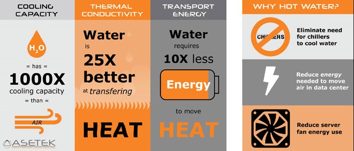
Learn why Liquid cooling is better than air cooling.
An example of a low pressure distributed pumping architecture is Asetek RackCDU which is currently installed at the most powerful HPC system in Japan today (JCAHPC’s Oakforest-PACS). In addition, OEMs and a growing number of TOP500 HPC sites (nine announced thus far) such as Lawrence Livermore National Laboratory, Los Alamos National Laboratory, Sandia National Laboratories and the University of Regensburg have addressed both the near term and anticipated cooling needs using hot water liquid cooling.
The direct-to-chip distributed cooling architecture addresses the full range of heat rejection scenarios. It is based on low pressure, redundant pumps and closed loop liquid cooling within each server node. This approach allows for a high level of flexibility.
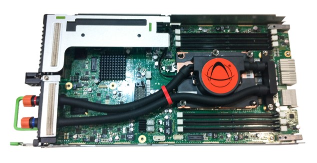
This distributed pumping approach is based on placing coolers (integrated pumps/cold plates) within server and blade nodes themselves. These coolers replace the CPU/GPU heat sinks in the server nodes to remove heat with hot water rather than much less efficient air. Asetek has over 4 million of these types of coolers deployed worldwide and, as of this writing, the MTTF of these pumps at production HPC sites in excess of 37,000 years.
Unlike centralize pumping systems, this approach isolates the pumping function within each server node, allowing for very low pressures to be used (4psi typical). This mitigates failure risk and reduces the complexity, expense and high pressures required in centralized pumping systems. In most cases, there are multiple CPUs or GPUs in a given node enabling redundancy at the individual server level as a single pump is sufficient to do the cooling.
Because of the low pressure, Asetek is able to use non-ridged tubing within the server allowing it to be quickly adaptable to OEM server designs. In addition, air cooled designs are able to be liquid cooled to support higher wattage CPU/GPUs without needing entirely new layouts.
This flexibility also means the liquid cooling circuit in the server can also easily incorporate memory, VRs and other high wattage components into the low PSI redundant pumping circuit.
The lowest data center impact is with server-level liquid enhanced air cooling (LEAC) solutions. Asetek ServerLSL™ replaces less efficient air coolers in the servers with redundant coolers (cold plate/pumps) and exhausts 100% of this hot air into the data center. It can be viewed as a transitional stage in the introduction of liquid cooling or as a tool for HPC sites to instantly incorporate the highest performance computing into the data center. At a site level, all the heat is handled by existing CRACs and chillers with no changes to the infrastructure.
While LEAC solutions isolate the liquid cooling system within each server, the wattage trend is pushing the HPC industry toward all liquid cooled nodes and racks. Enter Asetek’s RackCDU system which is rack-level focused, enabling a much greater impact on cooling costs for the data center. In fact, it is used by all of the current sites in the TOP500 using Asetek liquid cooling.
Asetek RackCDU™ provides the answer both at the node level and for the facility overall. RackCDU D2C (Direct-to-Chip) utilizes redundant pumps/cold plates atop server CPUs & GPUs, cooling those components and optionally memory and other high heat components. The heat collected is moved via a sealed liquid path to heat exchangers for transfer of heat into facilities water. RackCDU D2C captures between 60 percent and 80 percent of server heat into liquid, reducing data center cooling costs by over 50 percent and allowing 2.5x-5x increases in data center server density.
Heat management and removal is done by using heat exchangers to transfer heat, not liquid, to data center facilities water. RackCDU come in two types to give flexibility to cluster operators. InRackCDU™ is mounted in the server rack along with the servers themselves. Mounted in the top 3U or 4U of the rack (depending on overall heat load), it connects to Zero-U PDU style manifolds in the rack.
Most HPC clusters today utilizing Asetek technology use VerticalRackCDU™. This consists of a Zero-U rack level CDU (Cooling Distribution Unit) mounted in a 10.5-inch rack extension that includes space for 3 additional PDUs.
Beyond the rack, the hot water cooling in this architecture has additional advantages in the form of overall cost of heat removal. Because hot water (up to 40ºC) is used, the data center does not require expensive CRACs and cooling towers but can utilize inexpensive dry coolers. The system can, of course, also be connected to traditional cooled water systems (which is often done when there is available capacity).
The remaining heat in the data center air is removed by existing HVAC systems in this hybrid liquid/air approach. When there is unused cooling capacity available, data centers may choose to cool facilities water coming from the CDU with existing CRAC and cooling towers.
Distributed pumping at the server, rack, cluster and site levels deliver flexibility in the areas of heat capture, coolant distribution and heat rejection that centralized pumping cannot.
As HPC wattage trends continue to grow in 2017 and beyond, HPC sites can confidently focus on getting the most performance from their systems rather than worrying about whether their cooling systems are up to the task.


 Back to articles


